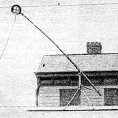
 but at the 1885 Toronto Exposition and in Montgomery Alabama in 1886 he used booms counter weighted about a centrally roof mounted pivot. He also used 1400 volts at 18 amps.
One fascinating aspect of trolleybus design history is that of the current collectors - the trolleybases in particular, and that is the subject of this article. Much overlaps with one of the trolleybus's step parents, the tram.
1880-1 - the beginnings
One, interestingly early reference to the idea of a trolleybus is in the Journal of the Society of Arts vol.XXIX, 1880-1, on page.574, written by Dr William Siemens, "Another arrangement by which an ordinary omnibus might be run upon the street would have a suspender thrown at intervals from one side of the street to the other, and two wires hanging from these suspenders; allowing contact-rollers to run on these two wires, the current could be conveyed to the tram-car, and back again to the dynamo machine at the station, without the necessity of running upon rails at all. "
William Siemens worked in England and had his three Siemens factories here, (he was big enough to go public in 1881). So could the idea for a trolleybus be just as much British as German? The article pre-dates the 1882 Halense experiments of his brother Werner Von Siemens. It certainly would seem that William and Werner were working together on this, as it also says in a reference (Transport World 5/12/53) "...Werner wrote to his brother William in England, asking him to obtain 50 iron telegraph posts of largest size." Sir William's company also supplied the equipment to the "first long electric tramway in the world" in Portrush, Northern Ireland, built between 1881-3 using hydro-electric power and sprung loaded rail collector shoes - so he was certainly involved in electric traction at this time. (Klapper, 1961) His achievements, which included the provision of Britain's first electric street lighting in Surrey, secured him the first presidency of the Institution of Electrical Engineers.
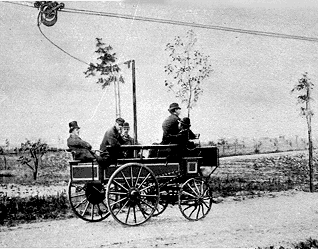 The father of the trolleybus is usually said to be Werner Von Siemens, because of his experiments in the Berlin suburb of Halense, between Charlottenburg and Spandau Bock (Berlin) for six weeks beginning 29 April 1882. This used a trolley or "contaktwagen" running on top of a pair of wires in horizontal configuration. "At a later stage an under-roller contact, on the lines of those used to-day, was introduced" (Transport World 5-12-1953).
In America, where the electrification of tramways was just beginning, Belgian Charles Van Depoele patented a under-running trolley wheel pressed against an overhead wire in 1882 in Chicago. He used over-running trolleys on trams in four cities  but at the 1885 Toronto Exposition and in Montgomery Alabama in 1886 he used booms counter weighted about a centrally roof mounted pivot. He also used 1400 volts at 18 amps.
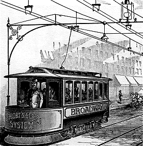
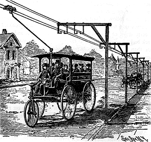

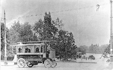
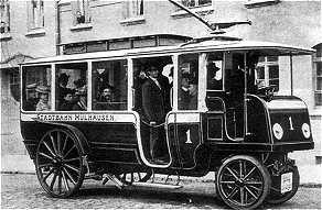 Meanwhile, Germany, and the mental father of the "trackless", Max Schiemann (1886-1933), was developing trolleybuses further in its own design engineering department. On 10 July 1901 he opened a 4 km long route in Saxonian Switzerland between Knigstein and Knigbrunn for 'public persons and goods traffic', the "Bielathal Motorbahn". He had developed the precursor of all modern trolleybus systems.
1909 - Britain
In 1909 a deputation from Leeds inspected the trolleybus system at Mulhausen incorporating a single boom (illus. Soper p.416). This was the design of Max Schiemann. They went on to Milan where they inspected the Filovia system "using a pair of trolley poles pressed against the overhead cables to keep the wheels in position", and also 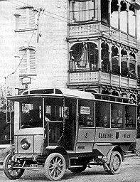 inspected the Cedes-Stoll system (see 1912) using a flexible cable and over-running trolley in Vienna (illus. Soper p.417).
By contrast the first British trolleybus, an R.E.T. demonstrated at Hendon on 25 September 1909, used both a trolley base and trolley head of great complexity and weight. Licenced from the Schiemann system, it incorporated a pair of trolley booms turning together upon a sort of turntable base, and linked at the top by another turntable carrying a trolley running under the pair of wires. I cannot see any justification for the complexity, though Soper reports (p.419) "the twin overhead wire system was demonstrated, but in order to avoid all possible danger, a third wire was contemplated. It was claimed that with a triple trolley head the electrification of the framework would be infallible and permanently avoided". For safety reasons, there was accommodation for third wire running at the Hendon trials.
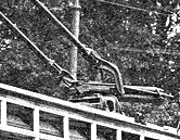 Be that as it may, it does draw attention to what must have been a problem with any trolley head combining both positive and negative polarity, namely that of insulation between the two, especially in wet weather. Because of this, apart from one or two single boom experiments, all subsequent British equipments using trolley booms had independent positive and negative booms each with its own trolley head.
The 1909 RET demonstration trolleybus in fact, had a unique version of the under-running Max Schiemann system - the booms were parallel to the body, with the leading boom 'steering' a circular trolley head casting that pivoted on the casting that joined the two booms. Insulation must have been complex. The trolleybase was a like a standard single deck tramcar base with a forward facing compression spring with an additional second spring superimposed under it to raise the leading boom. The base was thus single pivoted. Edward Munro, the Railless Company Chief Engineer, had had a patent granted, patent. No.764 of 12th January 1909, that comprised a self-aligning sprung base, a single boom and a double under-running trolleyhead, very different to that which famously was shown to the press a year later in MET's Hendon depot. Munro was still designing trolleybases in the 1920's.
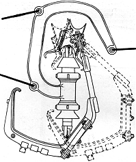
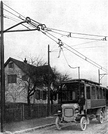 A minor disadvantage is that the J-hooks suspending the pair of wires have to be on one side only, and the framework of the trolley linking the upper pair of wheels to the lower bow has to be on the ''other" side.
Another disadvantage of all over-running trolleys is that junctions are near impossible, and also that replacement of the trolley after dewirement is very difficult.
The article on Lloyd-Kohler (Light Railway and Tramway Journal 5/5/1911) has extensive drawings of the collector system and says "The vertical position of the wire renders sidings and crossings exceedingly simple and reliable". There's a picture of a Lloyd-Kohler trolleybus on the Bremen Park line, crossing two tram lines, which appears to involve a upturned U casting with a 'gate' through which the trolleybus trolley wheel and bow passes. There's an unpublished picture of a siding that was withheld through lack of space, but has now been found. The collector weighed 12lbs, the wires were 11" apart and swoping collectors between oncoming buses "with a little practice takes at most fifteen seconds". There was a lever "by which a detachable cable contact box can brought within easy reach of the driver".
Up to 10 metres of flexible cable could be paid out "thus enabling the car to behave on the road with the ease of a self-propelled vehicle".
The English patents were "acquired by Brush Electric Manufacturing Co".
1911 - public service
Thus on 20 June 1911 when Leeds and Bradford simultaneously opened Britain's first trolleybus services the vehicles used had 'improved' bases.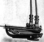
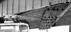 The trolleys of the Leeds and Bradford cars were of "Railless Electric Traction Co.'s double trolley type, complete with two poles and trolley heads, and capable of allowing the vehicle to run at a distance of not less than 15ft. from the centre of the trolley wires". (LRTJ, 7th July 1911) The trolley base was described as being two ordinary tramcar trolley heads, specially mounted and supplied by Brecknell, Munro and Rogers. Each base pivoted about a single mounting point.
However it appears from photographs that the springs did not turn with the base - probably because with the cumbersome springs and mountings employed this would have restricted the movement of the booms to either side. Later Leeds and Bradford (and Rotherham) trolleybuses were fitted with entirely new bases incorporating vertical springs. These would allow the booms to swing sideways until the boom fouled the neighboring base, i.e. nearly a right-angle to the line of travel, and would also be much simpler and lighter.
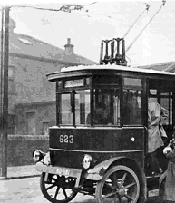 At least one of Dundee trolleys that later ran in Halifax used the original Railless/Brecknell trolleybases as the Bradford/Leeds vehicles up until 1926, so there was nothing inherently wrong with them. The trolley base on Bradford no.241, when converted to lorry in 1916, was converted to use vertical springs, perhaps because of the size of the cab. The bases used on no. 240, when converted to lorry, are not clear from the picture, but show 2 booms (King, 1994) and look like a standard tram base for skate running only in another (Brearley, 1957). The manager at Bradford, CR Spencer had at his disposal a large workshop for tramcars and although specifically banned from doing so, built trolleybuses that were considerably lighter than the RET cars.
He also designed the simpler, lighter vertical sprung trolleybases, so the two separate bases didn't engage each other. This solution doesn't seem to have stopped Leeds using standard tramcar bases when they built trolleybuses - bases with long horizontal front springs that must have hit each other when turning. (see Soper for pictures) although I've never read that they did. Max Schiemann had got round the problem at Bielethal, in Germany, 20 years before by heavily staggering the bases, one behind the other at some distance, although this must
have set up strange dynamics when turning, perhaps that's why he was trying a
single boom arrangement at Mulhausen in 1908. (Brearley, 1957)
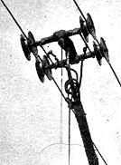 The "Filovia" system was intended to run alongside the Bradford RET system. The overhead was the same, but the current collector consisted of "a four wheel truck, placed on top of a boom, which is kept in contact with, and runs under the trolley wires in the same way as the ordinary tramway trolley wheel. Its design and construction have been so perfected that it will allow a displacement of the car to the extent of about 12 ft. from either side of the trolley wires, so that it will take easily very sharp curves, and will not leave the trolley wires even when running at a speed of 18mph.". (Railless Traction at Bradford, Light Railway and Tramway Journal, 7th April 1911). The photograph in the article is quite clear and similar to an upturned Cedes-Stoll trolley without the restraining hooks.
The impression is that the British Filovia was actually built. A drawing of the body for the car, shown in the article and reproduced in Geoff Lumb's "British Trolleybuses" "has been built by the United Electric Car Co.". It could be described as 'forward control' in layout, just like a tram. Electrically, it "is equipped by Dick, Kerr & Co. Ltd." Geoff states that the Filovia system, designed by Dr. Zani, who had a brother working at Dick, Kerr, was made by Societa Per La Trazione Electrica of Milan and licensed to a Manchester firm. UEC operated out of Trafford Park, Manchester (as well as Preston) but went bankrupt in 1911. Spencer, the Bradford manager, was twice overuled by his Tramways Committee from buying the vehicle. 3 months later, the Light Railway and Tramway Journal's article on the opening of Leeds and Bradford makes no mention of the Fliovia trolley. In April, 1912 the Filovia agency had passed to Watlington & Co, London, but no more is heard of it in this country. The systems in Italy were variously successful and some operated into the 1950s.
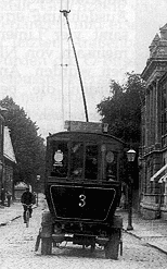 Single boom operation, however, despite experiments in Nottingham in the mid 30's (FP.Groves, 1975) and in Glasgow in the late 40's (B.Deans, 1978) seems to have worked well enough in Drammen in Norway. Introduced in 1909, it ran until 1967. An article appeared in Transport World in 1937. Line voltage was 550 volts and the wires were 6.1" apart. Short circuits with the wires so close together did "occur rather frequently". Pictures in a recent Norwegian publication show very sloppy overhead, but they seem to have persevered and perfected a system whose imperfection had led to "the gradual abandonment of other trolleybus services in Europe at the beginning of this century".
It was later discovered that small boys were throwing iron wire over the conductors and knocking them together with sledge poles! Perhaps too, the wind doesn't blow much in Drammen. The bases were made of "Special steel", with a single forward mounted compression spring, and had covered slip rings mounted on top of the single pivoting base, so that current was taken down through the roof - there had been problems of short circuiting through the wooden boards of the trolleybuses during the snowy winters. Ransomes trolleybuses were ordered in 1937 and 1950. No other Norwegian system had single poles.
1912 - Cedes-Stoll
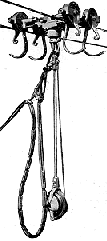 The over-running trolley attached to be bus by flexible cable still had its advocates. It was simpler and much lighter in weight than the cumbersome booms and bases, though still with the inherent disadvantage that overhead junctions were virtually impossible. And it had its own unique advantage that the flexible cable allowed the bus to manouevre in almost any way (provided it remained within reach of the overhead). Vehicles could for example reverse up a side street in order to turn round at any point on the route, thus in some degree overcoming the lack of junctions. Cedes-Stoll in conjunction with Brush demonstrated one of their vehicles at the M.T.A. conference in West Ham in 1912, and their system was adopted by Keighley in 1913, Aberdare in 1914 and also briefly by Hove in the same year. All these systems used a four-wheel over-running trolley.
Meanwhile Stockport, in 1913 adopted the Lloyd-Kohler system with wires in vertical configuration and a trolley having two wheels running on the upper wire and a bow contacting the lower wire.
The Trackless Trolley Ltd, claimed "great flexibility" in 1911 adverts for Cedes-Stoll, and an article in 1913 on the Stockport Lloyd-Kohler system states one set of wires was an advantage, with current gear being exchangeable at any convenient meeting place. These were the days, after all, when trolleybuses were seen only as feeders to tramways, not to be used in busy city centres, but serving "growing but scattered populations". (Aberdare Trackless Installation, Light Railway and Tramway Journal, 7th November 1913)
1912-1921 - refinement
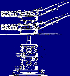 Like so much else in this story of design evolution, some ideas were not easily rejected. The advantage of a single pivot, if not a single boom, was championed up until the 30's. Estler Brothers of Victoria Docks in London, tramcar trolley equipment builders, who did have a connection with Brush, designed their superimposed trolleybase in 1912. It's always been stated that it was to avoid infringing Brecknell, Munro and Rogers patents, but the Estler trolleybase had it's own elegance and could turn through 360 degrees; a fact utilised by Keighley Corporation when they finally gave up Cedes-Stoll overhead but still had to turn out of a main road and into a narrow lane to get to the depot. (King, 1964)
The Estler patent didn't stop Garretts copying the arrangement which had been modified in 1921 and added a second slip ring to completely insulate the base - it had previously used the main casting for return current. The solution created greater height, which was to become a problem later for double deckers. Garretts, with their well preserved archive, present a fascinating insight into the research and development that was involved in perfecting trolleybases - work that went on after they had sold their last trolleybus. They solved the height problem in at least one instance, (Doncaster 1-4) by splitting the base in two,
which might have again created the possibility of entanglement on sharp bends,
although the bases were now insulated and so may not have short circuited.
1922 - the answer
So the trolley boom, based upon the original Schiemann under-running system finally triumphed, though with many modifications over the years. The use of vertical springs has already been mentioned. These were of some height so were not used on double-deck vehicles, for which bases with compression springs projecting horizontally in front were used - for trams and trolleybuses alike. Another development borrowed from the tram was the use of a trolley mast, one for each boom, and mounted on the floor of the lower deck or upper deck. These . patent cam. types had the special advantage of transferring the heavy weight of the trolley gear (not to mention shock loading in the case of dewirement) from the comparatively flimsy roof structure of the vehicle. In fact modern trolleybuses all incorporate some form of trolley gantry to transfer the load from the roof itself at least to the side pillars.
Some were built into the roof structure, but many were separate, with the advantage of minimising noise transmission.
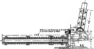
![]() The compression spring (projecting to the front) had the advantage of "going solid" if it should break, so preventing the trolley crashing down on to the roof or to either side perhaps causing injury. But when the trolley deviated to either side the projecting spring fouled the adjoining trolley base preventing deviation to anything like 90°. Compression springs require control to prevent buckling so tend to occupy more space than tension springs The next development was to use tension springs projecting horizontally to the rear, which allowed the trolley to reach more nearly to 90° deviation, whilst improved quality of the springs themselves reduced the risk of breakage.
The compression spring (projecting to the front) had the advantage of "going solid" if it should break, so preventing the trolley crashing down on to the roof or to either side perhaps causing injury. But when the trolley deviated to either side the projecting spring fouled the adjoining trolley base preventing deviation to anything like 90°. Compression springs require control to prevent buckling so tend to occupy more space than tension springs The next development was to use tension springs projecting horizontally to the rear, which allowed the trolley to reach more nearly to 90° deviation, whilst improved quality of the springs themselves reduced the risk of breakage.
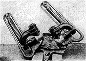 The 'patent cam' reference comes from a Railless brochure of around 1923 that states "The current collecting gear consists of the improved type of railless patent cam-controlled trolleybase, which is bolted to a stout roof plank fitted for the purpose. This type of base is an improvement on the old type, which necessitated channel supports". Railless's Mr. Munro was still experimenting and brought out this horizontal version at this time - the old version being the type fitted to Rotherham 41-43 and on double deckers right up to Birmingham 14 fifteen years later. (Interestingly Ipswich 5, always referred to as a Tilling-Stevens, had these horizontal bases, the only non-Railless trolleybus to be so fitted; were they spares ordered for the earlier Railless? These bases were replaced by Estler trolleybases in 1931.
The ultimate solution - why did nobody think of it before? - was to use inclined springs more or less parallel to the trolley boom (especially so when the booms were low). The overall height of the base was as low as any, and, most important, there were no springs projecting to front or rear so that provided the overhead wires were at normal height, the trolley could deviate to 90° and beyond. In fact a stop was provided near the straight-ahead position so that it could not make a complete circle which would have twisted the cable. This base, which was known as the Brecknell-Willis "Light-weight" also presumably had the
additional advantage of lightness, became from 1933 onwards the standard for all
systems.
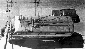 The Brecknell,Willis 'new' design was brand new in 1933, first appearing, I think, on London United 61 in March of that year. (The last "Diddler" no.60 was also so fitted, but it's not known when this was, or if it was experimentally fitted to gain running experience.) An AEC/English Electric advert of December 1933 even shows No.61 with the 'old' Brecknell,Willis 'low' type and trolleybuses were supplied with this superseded design up until 1935 (on Wolverhampton no.210).
Also in 1935, there was a strange design by GD.Peters (of air brake fame) for an articulated trolley method. Neither Brian Dyes of Ipswich Transport Museum (who rescued the 4 drawings from Tees-side) or I can understand either the point or how it works! By the mid-30's the spirit of invention, at least as far as the fundamental design of trolleybases for trolleybuses was concerned, was no longer necessary. Since then, innovation has been mainly concerned with retrieving errant booms, using hydraulics and with new lightweight materials. The long gestation was over.
Written by Ashley Bruce and John Senior, August-December 1999. Minor corrections, May 2025
